KakuteF4-AIO
Description
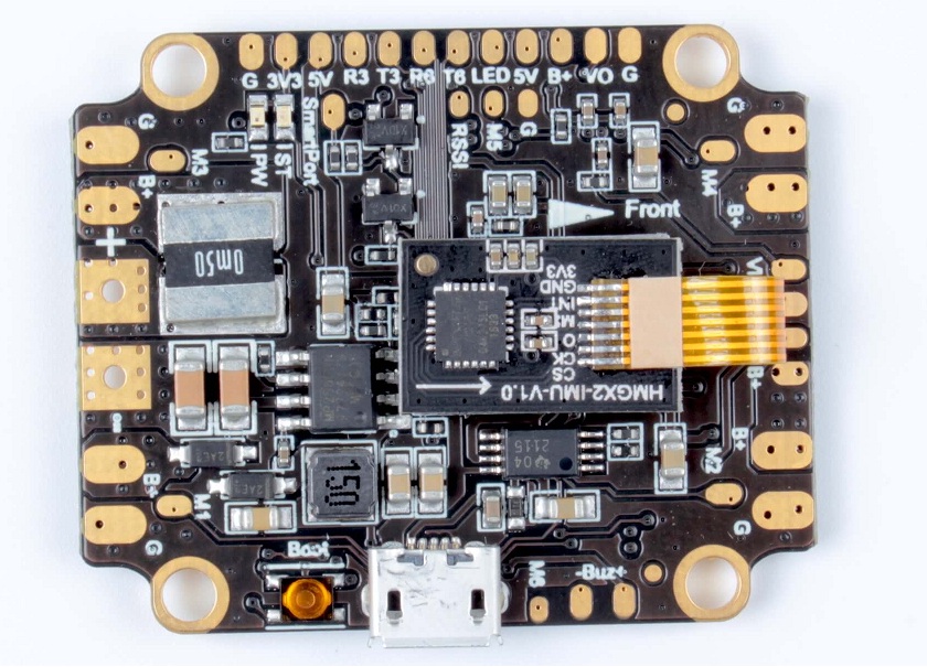
The Holybro Kakute F4 All-In-One flight controller makes it easy to build your multirotor. It integrates flight controller (FC), power distribution board (PDB), and on-screen display (OSD) in one. The Kakute F4 AIO’s layout makes it easy to wire up the other components of the multirotor while keeping the build neat and tidy.

Features
•Supports Betaflight and Cleanflight.
•Betaflight OSD. Change PIDs, adjust common configuration parameters, and change video transmitter channel and power level, all using your transmitter sticks and goggles.
•Soft-mounting built in. The “gyro” chip on this board is mounted on vibration-isolating foam. This means that there is no need to soft-mount the board itself.
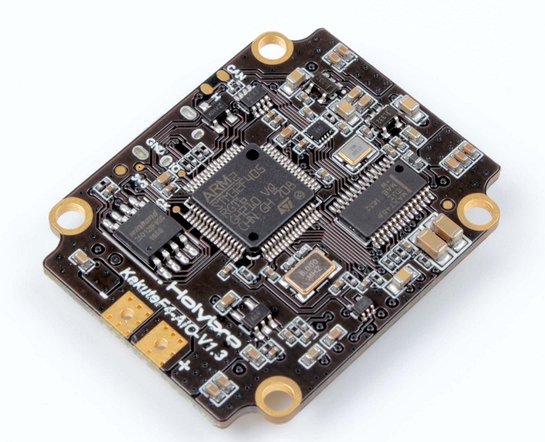
•New high-performance / low-noise / high sensitivity IMU. ICM20689 with 6-axis gyro and accelerometer. Can run at up to 32 kHz.
•2 oz copper PCB allows up to 120A maximum continuous current.
•Dedicated bootloader button for easy firmware flashing.
•Low-profile design fits into even very compact frames.
•Input voltage 7v to 42v. Power the board directly from the flight pack, up to 6S (on “BAT” pad only).
•Automatic voltage monitoring. No need to run a separate vBat wire for voltage monitoring; the Kakute F4 AIO monitors voltage directly from the battery power lead.
•Filtered voltage output for clean, noise-free video. On-board regulators output 5v at up to 1.5 amps and 3.3v at up to 200 mA to power peripherals such as receiver, video transmitter, FPV camera, or LED strip.
•Supports BLHeli passthrough for easy ESC upgrade and configuration.
Image

Specifications
•MCU: STM32F405RGT6 32-bit processor
•IMU: ICM20689 (SPI)
•Baro: BMP280 (Only V2 support)
•USB VCP Driver (all UARTs usable simultaneously; USB does not take up a UART)
•hardware UARTS (UART1/3/6 for V1, UART1/3/4/5/6 for V2)
•128 Mbit Dataflash chip for Blackbox logging
•Dimensions: 35x43x6mm (includes USB in height)
•Mounting Holes: Standard 30.5mm square to center of holes
•Weight: 7g
Pinout Diagram
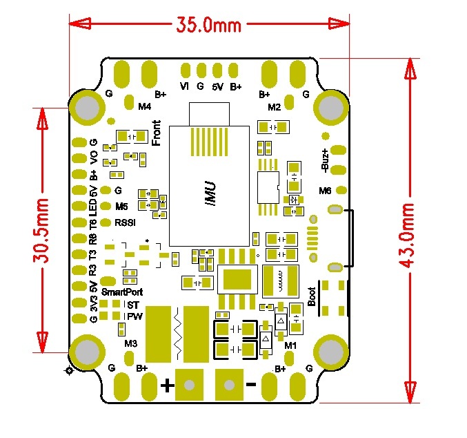
BUZ- : Piezo buzzer negative leg

BUZ+ : Piezo buzzer positive leg

LED       : WS2182 addressable LED signal wire

SmartPort : FrSky SmartPort Telemetry

R3, T3    : UART3 RX(with sbus invertor) and TX

R6, T6    : UART6 RX and TX

RSSI      : Analog (0-3.3v) RSSI input

3V3       : 3.3v output (200 mA max)

5V        : 5v output (1.5 A max)

M1 to M6  : Motor signal outputs

VO        : Video output to video transmitter

VI        : Video input from FPV camera

Boot      : Bootloader button

G         : Ground

B+        : Battery positive voltage (2S-6S)

+         : Main battery lead positive

-         : Main battery lead negative
Target Code
KAKUTEF4
Hardware Designs (if available)
The hardware is currently closed source.
Manufacturers and Distributors
www.holybro.com (Manufacturer & Designer)
Distributors:
FAQ & Known Issues
“Board Align” Feature Documentation
https://www.youtube.com/watch?v=jSzWRnAqsSY
How To Check For Continuity With Your Multimeter
https://www.youtube.com/watch?v=MZ8YxBMQI5Q
All About Betaflight Drivers, Including How To Install Them
https://www.youtube.com/watch?v=m4ygG6Y5zXI
SmartPort:
Kakute F4's bidir inverter is designed with mosfet.We have tested the smartport of each board with XSR receiver and X9D in factory. But there are some special XSR receivers, who's input capacitance are higher than the normal, it may cause the smartport waveform distorted. The waveform don't drop to 0v during low period. See the following picture.

Change a resistor on the KakuteF4 from 4.53K to 2.2K, the waveform looks good. That may be the reason.


If the SmartPort don't work stable, please try this way. If you don't have a SMD resistor, you can use a 5.1K plug-in resistor to bypass SmartPort signal to GND. It has the same effect.
And we have changed this resistor from 4.53K to 2.2K at the secondary produce.
Other Resources
Manual: http://www.holybro.com/manual/Holybro_Kakute_F4_AIO_Manual_v1.4.pdf
Discussion: https://www.rcgroups.com/forums/showthread.php?2904475-Holybro-Kakute-F4-AIO-Flight-Controller
Contact us at:
•Email: productservice@holybro.com
•Facebook Page: Holybro
•Facebook Group: Holybro Hobby Official Group